circuits
schematics
diagrams
FreeCircuits.net

Integrator
By internum

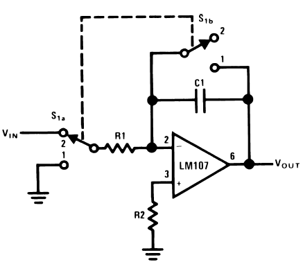
Figure 1. Integrator

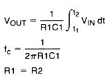
For minimum offset error due to input bias current
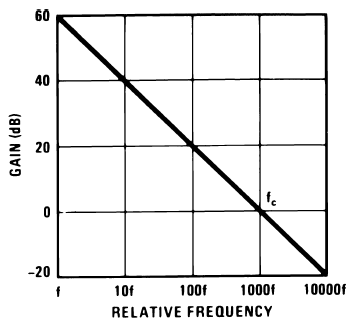
The integrator is shown in Figure 1 and performs the mathematical operation of integration. This circuit is essentially a low-pass filter with a frequency response decreasing at 6 dB per octave. An amplitude-frequency plot is shown in Figure 2.

Figure 2. Integrator Frequency Response
The circuit must be provided with an external method of establishing initial conditions. This is shown in the figure as S1. When S 1 is in position 1, the amplifier is connected in unity-gain and capacitor C1 is discharged, setting an initial condition of zero volts. When S1 is in position 2, the amplifier is connected as an integrator and its output will change in accordance with a constant times the time integral of the input voltage.
The cautions to be observed with this circuit are two: the amplifier used should generally be stabilized for unity-gain operation and R2 must equal R1 for minimum error due to bias current.
 1555
1555 ![]() 09 December 2007
09 December 2007
