circuits
schematics
diagrams
FreeCircuits.net

Audio Indicator
By Andy Collinson
Audio Indicator circuit
Notes:
If you need to monitor some audio signal at a location that is either soundproof
are too far away to actually hear the signal then you can use a circuit similar
to this one. A remote indication that the audio source is active is provided
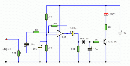
visually, here in the form of a LED. Referring to the above circuit, the 10k
preset is a level control which should be adjusted so that when the source (
audio signal or alarm ) is producing the desired amount of noise, the LED lights.
The input stage is an inverting x100 amplifier made with a 741 op-amp. The
output of the 741 is capacitively coupled into a 10k load resistor, thus
removing any dc component from the signal and the offset null voltage of the op-amp.
As only the amplified audio signal appears across the 10k load resistor, this is
half wave rectified by the 1N4148, filtered by the 10u capacitor, and this small
dc voltage used to directly drive the 2N2222A transistor, lighting the LED. Any
NPN transistor may be used in replacement of the 2N2222, and should work with
any transistor having a current gain of over 100. Examples include, BC107/8/9,
BC547/8, ZTX300, 2N3904 etc. The sensitivity of this circuit is high, and input
signal level as low as 10mV RMS will light the LED. If the monitored audio
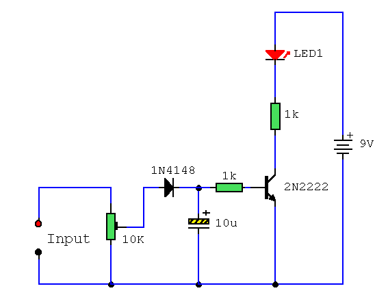
signal level is much higher than this (i.e. 1000mV and higher) then the
following simpler circuit may be used.

Peak Monitor:
To use either circuit as a peak monitor adjust as follows. For example suppose the input signal is from an audio power amplifier. Audio voltages higher than 1 Volt may easily be generated at the loudspeaker output, so the second circuit is used and connected directly across the loudspeaker terminals. You adjust the volume of the audio power amplifier until the level is uncomfortable or to any desired level. You then adjust the preset so that the LED lights. You then return the volume control to a normal level. If this accidentally gets turned up the LED will light providing visual indication that the peak level has been reached.
 2900
2900 ![]() 08 December 2007
08 December 2007

