circuits
schematics
diagrams
FreeCircuits.net


Four channel RF remote control
By internum
Figure 1. RF 4 channels remote transmitter circuit
This is a very simple RF transmitter circuit that consists of the Holtek HT-12E encoder chip and AM 418MHZ-transmitter module (WZ-X01). Using the hybrid RF xmit/receive modules make building the RF remote control a lot easy.
The transmitter can be powered with any voltage from +3 to +12V. The total current consumption is less than 5ma. Depending on the supply voltage, you may need to select a difference resistance value for the oscillator resistor R1. The recommended oscillator is Foscd (decoder) = 50 Fosce (encoder). See data sheet for more details.
The individual security code of the transmitter is preset by dip-switches S5, up to 256 combinations.
When any of S1-S4 is pressed the /TE pin is pulled low, and power is applied to both the encoder chip and transmitter module, the encoder then starts scanning and transmitting the status of the 12bits address and data serially.
Figure 2. RF 4 channels receiver circuit
The circuit diagram for the receiver (WZ-R01)is shown in figure 2. The decoder U1(HT-12D) receives serial addresses and data from the encoder that are transmitted by the RF transmitter module. It compares the serial input data three times continuously with its local addresses. If no error or unmatched codes are found, the input data codes are then decoded and transferred to the output pins D8~D11. The VT pin also goes high to indicate a valid transmission, which will turn on the LED1. The addresses of the decoder (set by S1) have to be matched with the transmitter encoder. The outputs of U1 drive the four TIP30 PNP transistors that can be connected to the relays or lamps.
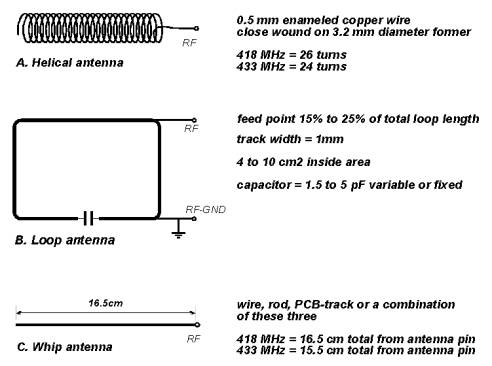
The operating range of this transmitter/receiver is dependent on the choice and position of the antenna. The space around the antenna is as important as the antenna itself. Try to keep the antenna away from other metal in the system such as batteries and PCB ground plane. The following types of antenna are recommended.
Antenna Configuration:
 36928
36928  28 August 2007