circuits
schematics
diagrams
FreeCircuits.net


Simple receiver with microvolt sensitivity
By Charles Kitchin
The three-transistor circuit in Fig 1 costs less than $10 to build, uses commonly available components, and consumes less than 10 mA from a single 9V battery. If you wind coil L1, as the figure shows, the circuit receives signals in the 5- to 15-MHz short-wave band. You can add turns to or subtract turns from L(or change C2) to receive other frequencies.
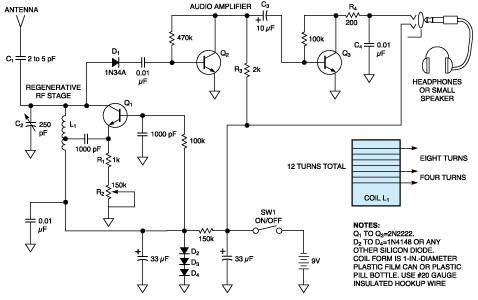
Figure 1. Receiver circuit diagram
Q1, a 10Сћ bipolar transistor, acts as a high-gain regenerative stage and amplifies microvolt-level signals at the antenna up to hundreds of millivolts to drive diode-detector D1. In addition to providing high gain, regeneration also greatly increases the Q (selectivity) of the circuit, producing a high-Q circuit, which can use low-cost coils (or free hand-wound coils).
Using a high-transconductance bipolar transistor for Q1 rather than a vacuum tube or JFET provides much more gain per microamp of current. However, in previous bipolar circuits of this type, the regeneration level has been difficult to control. In this circuit, R1 and R2 provide a large amount of negative bias at the emitter of Q1 to achieve smooth control. Rallows for user control of the regeneration. You should adjust the pot so that Q1 is just at the threshold of oscillation where both gain and selectivity are maximum.
Q2and Q3, a two-transistor amplifier, which has sufficient output level to directly drive headphones or a small speaker, amplify the detected audio signal output from D1. R3can become a volume control if you replace it with a 2-kOhms potentiometer and connect C3to its wiper. R4 and C4 form a lowpass filter that maintains circuit stability and improves the receiver's sound quality. D2, D3, and D4 implement a low-cost voltage regulator to keep the voltage supplying Q1fairly constant, which minimizes drift.
This receiver works with a short whip antenna, which you can connect directly to the top of tuning-capacitor C2, or you can use an outside antenna for better reception. When you use an external antenna, Cmust decouple the antenna's capacitance from L1. The regenerative stage of Q1operates at less than 30 ВµW (50 ВµA at 0.6V). This low power, combined with the use of a small capacitor for C1, prevents the detector (if it oscillates) from interfering with other receivers in the area. This problem was common in the 1920s and 1930s when tube-type regenerative receivers of this type, dissipating several watts of power, caused interference.
 www.edn.com
  16559
16559  28 August 2007