circuits
schematics
diagrams
FreeCircuits.net

Simple Low-pass Filter
By internum
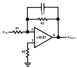
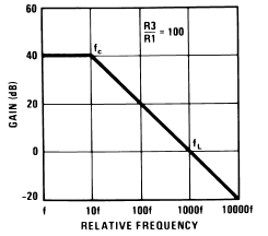
The simple low-pass filter is shown in Figure 1. This circuit has a 6 dB per octave roll-off after a closed-loop 3 dB point defined by fc. Gain below this corner frequency is defined by the ratio of R3 to R1. The circuit may be considered as an AC integrator at frequencies well above fc; however, the time domain response is that of a single RC rather than an integral.

Figure 1. Simple Low Pass Filter

R2 should be chosen equal to the parallel combination of R1 and R3 to minimize errors due to bias current. The amplifier should be compensated for unity-gain or an internally compensated amplifier can be used.

Figure 2. Low Pass Filter Response
A gain frequency plot of circuit response is shown in Figure 2 to illustrate the difference between this circuit and the true integrator.
 1558
1558 ![]() 09 December 2007
09 December 2007
