circuits
schematics
diagrams
FreeCircuits.net


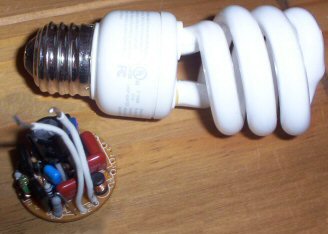
14 Watt Compact Fluorescent Electronic Ballast
By Robert Dvoracek
Info:
It is a rather interesting oscillator circuit which I will attempt to explain the operation of. However, I don't fully understand it, so if someone else does please contact me at the above e-Mail address so that the aspiring electronics experimenters who visit these pages may expand their understanding. On the other hand, if I got it right, also please tell me, or if you have anything to add to the explanation.
14 Watt Compact Fluorescent Electronic Ballast circuit
Description:
As the power comes in, it is filtered by L1 and a .1uF capacitor. A .47 Ohm reisitor is also provided and is probably fusible. It is then rectified by the bridge formed by D1-D4 and filtered by a 10uF capacitor. As power is first applied, a 100nF 63V capacitor begins charging through a 470k reisitor. Once this capacitor reaches 32V, the DIAC breaks over turning on Q2. Power then flows through Q2, the top winding of T1, L2, a filament of fluorescent bulb FL1, a 4.7nF capacitor, the other filament of FL1, and a .1uF capacitor, current being limited by L2 and the resistance in the filaments. Transformer action also begins inducing power in the other 2 windings of T1. This tends to begin to turn on Q1 and turn off Q2. Once Q1 is on, the charge that has built up in the .1uF and 4.7nF capacitors attached to FL1 begins flowing back the other way through the filaments, L2, the top turn of T1 and Q1. This once again induces power into the other two windings of T1 except in the opposite direction, eventually turning off Q1 and turning on Q2. The 470pF capacitor and other 470k resistor apparently make sure that both transistors are not on at the same time. Otherwise, it would be a dead short! Once the arc starts, most of the current flows directly between the filaments instead of through them. Only a small amount flows through them to keep them warm.
Notes:
All of the inductors and T1 are very small ferrites. In fact, the entire circuit is only 1 3/8" across. Everything is packed in and the filter capacitor is actually raised from the board by its leads to make space for other components underneath. L1 is 85 turns of 25-30AWG magnet wire on a round I shaped ferrite core. The core is 2mm in diameter and the top and bottom are 5mm diameter with 4mm in beteween where the coil is wound. L2 is 150 turns of 25-30AWG magnet wire on an E core with a 1mm gap precut in the center leg of one of the halves. The center leg measures 6 x 2.5mm in thicknesss. The outer legs measure 6 x 2mm. When the halves are put together, they are 13mm wide and 12mm tall. T1 is a tiny ferrite torroid with a 3mm hole, 6mm total diameter and is 3mm thick. Each of the 3 windings are 3 turns, counted in the usual way by the number of times the wire passes through the hole.
The circuit can be reused to successfullly power a T18 18" straight fluorescent bulb when your original spiral bulb goes. It should work with any fluorescent light that's around 14 watts and produces an arc around 18" long. In operation, the ballast seems to make one of the filaments run hotter than the other. This would seem to explain the failure mode of the original bulb because it had a bad filament. My bulb only lasted 3 years instead of the advertised 7. This could be from a DC component to the waveform. A simple check with an oscilloscope would verify this. Some of the other bulbs in the same fixtures are still going, so this problem seems to plague some and not others.
Shahid Ali writes:
> Hello,
> What are the changes
will i have to make to the14 Watt
> Compact Fluorescent Electronic Ballast circuit to run it on 220v ???
> Please can you help me???
Yes, very good to hear from you Mr. Ali. A good start would be to double the resistances and make sure your capacitors are up to the task. Just remember that when you rectify an AC sine wave that you will get 1.414 times the RMS voltage which in your case will be around 311.08V. To be safe, they should be at least 400V except the 100n which doesn’t need to be changed. The same goes for the transistors. I believe that as voltage increases, the frequency increases as well, so L2 and T1 shouldn’t need to be changed. You may have to experiment with this.
 kickme.to/lightningstalker
  22860
22860  08 December 2007