circuits
schematics
diagrams
FreeCircuits.net

Triangle-Wave Generator
By internum
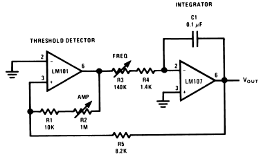
A constant amplitude triangular-wave generator is shown in Figure 1. This circuit provides a variable frequency triangular wave whose amplitude is independent of frequency.

Figure 1. Triangular-Wave Generator
The generator embodies an integrator as a ramp generator and a threshold detector with hysterisis as a reset circuit. The integrator has been described in a previous section and requires no further explanation. The threshold detector is similar to a Schmitt Trigger in that it is a latch circuit with a large dead zone. This function is implemented by using positive feedback around an operational amplifier. When the amplifier output is in either the positive or negative saturated state, the positive feedback network provides a voltage at the non-inverting input which is determined by the attenuation of the feedback loop and the saturation voltage of the amplifier. To cause the amplifier to change states, the voltage at the input of the amplifier must be caused to change polarity by an amount in excess of the amplifier input offset voltage. When this is done the amplifier saturates in the opposite direction and remains in that state until the voltage at its input again reverses. The complete circuit operation may be understood by examining the operation with the output of the threshold detector in the positive state. The detector positive saturation voltage is applied to the integrator summing junction through the combination R3 and R4 causing a current I+ to flow.

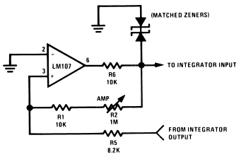
Figure 2. Threshold Detector with Regulated Output
The integrator then generates a negative-going ramp with a rate of I+/C1 volts per second until its output equals the negative trip point of the threshold detector. The threshold detector then changes to the negative output state and supplies a negative current, I−, at the integrator summing point. The integrator now generates a positive-going ramp with a rate of I−/C1 volts per second until its output equals the positive trip point of the threshold detector where the detector again changes output state and the cycle repeats.
Triangular-wave frequency is determined by R3, R4 and C1 and the positive and negative saturation voltages of the amplifier A1. Amplitude is determined by the ratio of R5 to the combination of R1 and R2 and the threshold detector saturation voltages. Positive and negative ramp rates are equal and positive and negative peaks are equal if the detector has equal positive and negative saturation voltages. The output waveform may be offset with respect to ground if the inverting input of the threshold detector, A1, is offset with respect to ground.
The generator may be made independent of temperature and supply voltage if the detector is clamped with matched zener diodes as shown in Figure 2.
The integrator should be compensated for unity-gain and the detector may be compensated if power supply impedance causes oscillation during its transition time. The current into the integrator should be large with respect to Ibias for maximum symmetry, and offset voltage should be small with respect to Vout peak.
 11913
11913 ![]() 10 December 2007
10 December 2007
