Electronic
circuits
schematics
diagrams
circuits
schematics
diagrams
FreeCircuits.net


Positive Peak Detector with Buffered Output
By Robert J. Widlar
The peak detector is similar in many respects to the sample-and-hold circuit.
The peak detector in Figure 1 is similar in many respects to the sample-and-hold circuit. A diode is used in place of the sampling switch. Connected as shown, it will conduct whenever the input is greater than the output, so the output will be equal to the peak value of the input voltage. In this case, an LM102 is used as a buffer for the storage capacitor, giving low drift along with a low output resistance.
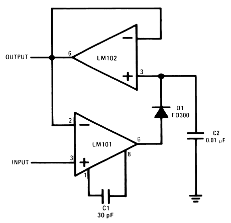
Figure 1. Positive Peak Detector with Buffered Output
As with the sample and hold, the differential input voltage range of the LM101 permits differences between the input and output voltages when the circuit is holding.
 4561
4561  08 December 2007