circuits
schematics
diagrams
FreeCircuits.net

Tracking Regulated Power Supply
By internum
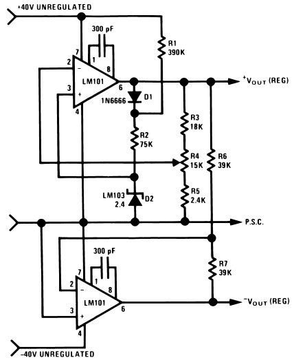
A tracking regulated power supply is shown in Figure 1. This supply is very suitable for powering an operational amplifier system since positive and negative voltages track, eliminating common mode signals originating in the supply voltage. In addition, only one voltage reference and a minimum number of passive components are required.

Figure 1. Tracking Power Supply
Output voltage is variable from ±5V to ±35V.
Negative output tracks positive output to within the ratio of R6 to R7.
Power supply operation may be understood by considering first the positive regulator. The positive regulator compares the voltage at the wiper of R4 to the voltage reference, D2. The difference between these two voltages is the input voltage for the amplifier and since R3, R4, and R5 form a negative feedback loop, the amplifier output voltage changes in such a way as to minimize this difference. The voltage reference current is supplied from the amplifier output to increase power supply line regulation. This allows the regulator to operate from supplies with large ripple voltages. Regulating the reference current in this way requires a separate source of current for supply start-up. Resistor R1 and diode D1 provide this start-up current. D1 decouples the reference string from the amplifier output during start-up and R1 supplies the start-up current from the unregulated positive supply. After start-up, the low amplifier output impedance reduces reference current variations due to the current through R1.
The negative regulator is simply a unity-gain inverter with input resistor, R6, and feedback resistor, R7.
The amplifiers must be compensated for unity-gain operation.
The power supply may be modulated by injecting current into the wiper of R4. In this case, the output voltage variations will be equal and opposite at the positive and negative outputs. The power supply voltage may be controlled by replacing D1, D2, R1 and R2 with a variable voltage reference.
 1741
1741 ![]() 10 December 2007
10 December 2007
