circuits
schematics
diagrams
FreeCircuits.net
 Wireless Transmitter")

AV (Audio/Video) Wireless Transmitter
By internum
AV (Audio/Video) Wireless Transmitter
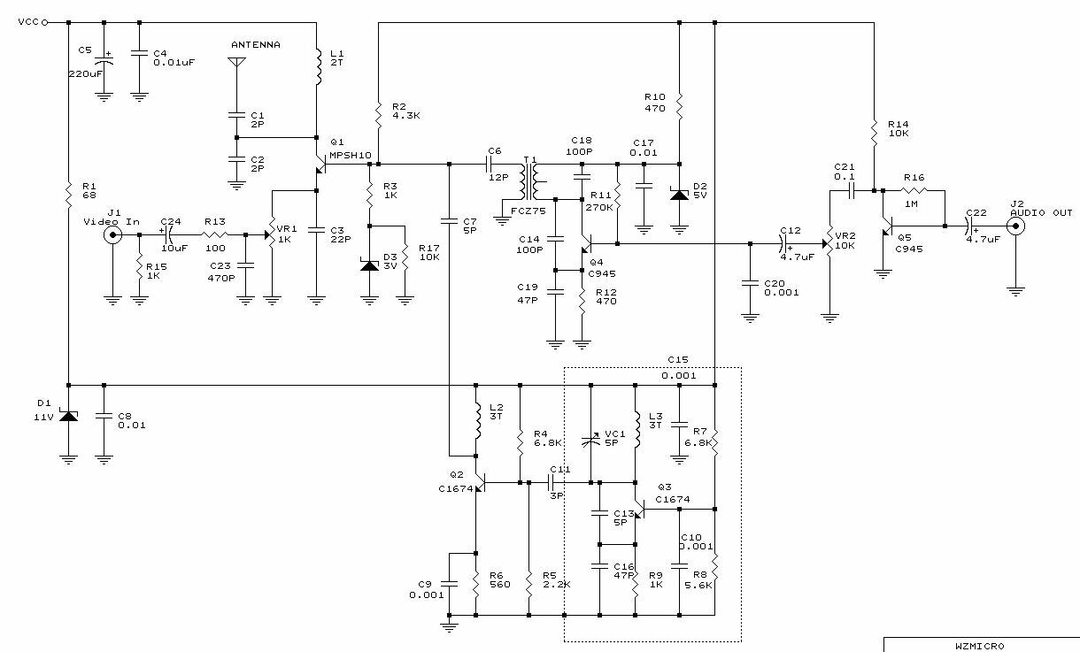
Circuit Analysis:
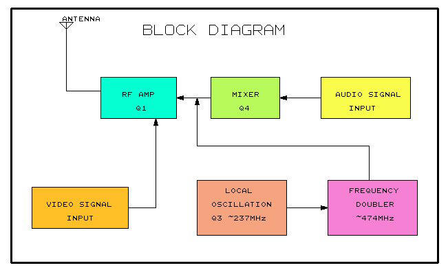
Q3, VC1, C13, C16 and L3 all make up a colpitts oscillator circuit that fluctuates form 220~250MHz. You can regulate the frequency to any value within this threshold by tuning VC1 or L3. C13 modulates the signal rate. When the capacitance increases, so does the modulation. R9 and C16 bias the local oscillation. If you lower R9's frequency to 680W the oscillator's output level will increase.
Q2 and L2 act as a frequency doubler. C7, along with FCZ7S3R5 (IF transformer), the Q4 transistor, C14, C19 and R12 all make up the mixer. This mixer takes both audio and visual signals together and "mix" them into one and passes through RF Amplifier Q1 to transmit the signal to the antenna.
Testing:
1. Turning the blue component's trimmer on VC1 varies the frequency. When we turn the trimmer, the television's channel has to be changed accordingly. It is easier to tune the A/V Sender if you have a spectrum analyzer to help you find the correct frequencies. If the frequency is tuned to 474 MHz then this would be the equivalent of your TV's channel 14 UHF band.
2. The IF transformer is used to synchronize the audio and video frequency's level radio. If the TV's image is too blurry then you can adjust the IFT to fine-tune the image.
3. SVR1 controls the video signal input ratio, while SVR2 controls the audio portion. You can tune these components according to your needs.
 16248
16248  05 August 2007