circuits
schematics
diagrams
FreeCircuits.net

Nonlinear Operational Amplifier
By Robert J. Widlar

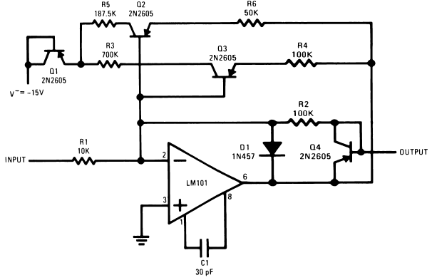
Figure 1. Nonlinear Operational Amplifier with temperature-compensated
breakpoints
A method of producing very sharp, temperature-stable breakpoints in the transfer function of an operational amplifier is shown in Figure 1. For small input signals, the gain is determined by R1 and R2. Both Q2 and Q3 are conducting to some degree, but they do not affect the gain because their current gain is high and they do not feed any appreciable current back into the summing mode. When the output voltage rises to 2V (determined by R3, R4 and V−), Q3 draws enough current to saturate, connecting R4 in parallel with R2. This cuts the gain in half. Similarly, when the output voltage rises to 4V, Q2 will saturate, again halving the gain.
Temperature compensation is achieved in this circuit by including Q1 and Q4. Q4 compensates the emitter-base voltage of Q2 and Q3 to keep the voltage across the feedback resistors, R4 and R6, very nearly equal to the output voltage while Q1 compensates for the emitter base voltage of these transistors as they go into saturation, making the voltage across R3 and R5 equal to the negative supply voltage. A detrimental effect of Q4 is that it causes the output resistance of the amplifier to increase at high output levels. It may therefore be necessary to use an output buffer if the circuit must drive an appreciable load.
 1655
1655 ![]() 08 December 2007
08 December 2007
