Electronic
circuits
schematics
diagrams
circuits
schematics
diagrams
FreeCircuits.net

Monitor Splitter
By Miroslav Adzic
A Simple Splitter Driving Two (or even more) PC Monitors.
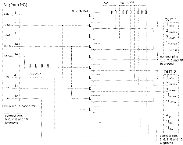
Monitor Splitter circuit
The signal sources in the analog output stage of the PC SVGA card see the right impedance - 75 ohms on each line (five resistors), and the input impedances of the transistors are so high that they do not make any significant additional load.The three ID lines can be omitted. If used, they should be connected to the cheaper (less advanced) of the two monitors.
The transistors that form the ten emitter-followers should be as fast as possible. 2N3906 is not the best possible choice, but it does the job and is unusually cheap (for such a versatile component).
All connections should be as short and straight as possible. Monitor signals are RF, so the splitter should be put in a metal case which is connected to the circuit ground. It should be supplied with well-filtered 5 volts and some 600 mA.
There is some DC component in the ouput signals, but it should not be a problem. The splitter works fine at 800x600 and 1024x768 on 15" monitors. For higher pixel-rates maybe it would be preferable to use faster transistors (haven't tried). High gain is also a good thing, because it gives emitter-followers higher input resistances.
 1914
1914 ![]() 08 December 2007
08 December 2007

